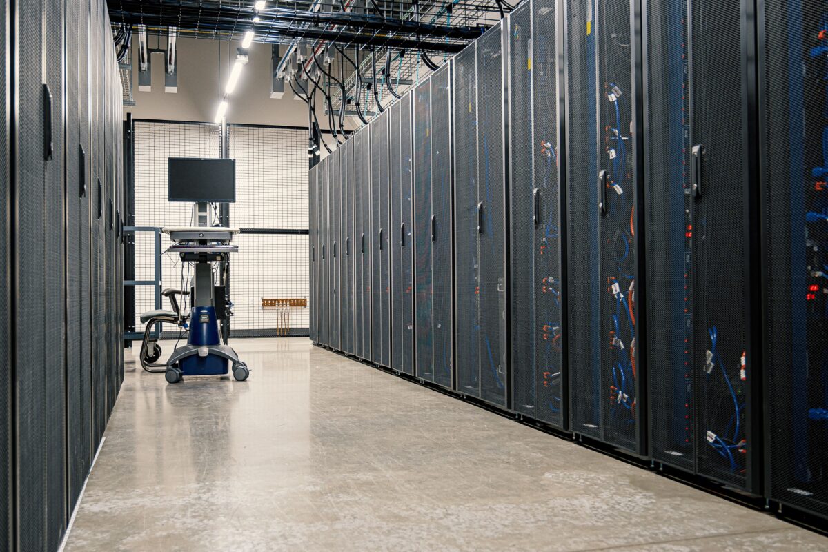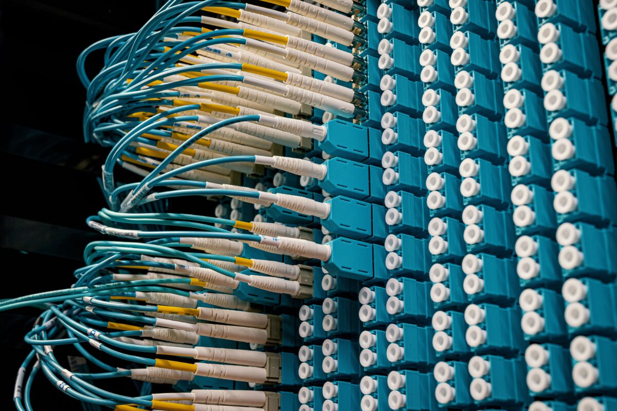
A data center may look like a large building filled with server racks, but its architecture is much more complex than a collection of computers.
A modern data center is an interconnected system of compute, networking, storage, power, cooling, security, and management infrastructure.
The four most important technical building blocks are often easier to understand as:
                 DATA CENTER
                      |
       ┌──────────────┼──────────────┐
       ↓              ↓              ↓
    Compute        Network        Storage
       │              │              │
       └──────────────┼──────────────┘
                      ↓
                    Power
                      +
             Cooling & Facility
Compute performs the work.
The network moves data.
Storage holds data.
Power keeps everything running.
None of these systems can be designed independently.
A faster server is not very useful if the network becomes a bottleneck. A powerful storage system cannot operate without sufficient power and cooling. And a data center with excellent hardware still needs redundancy and management systems to remain available when components fail.
This is why data center architecture is really about how multiple infrastructure layers work together.
What Is Data Center Architecture?
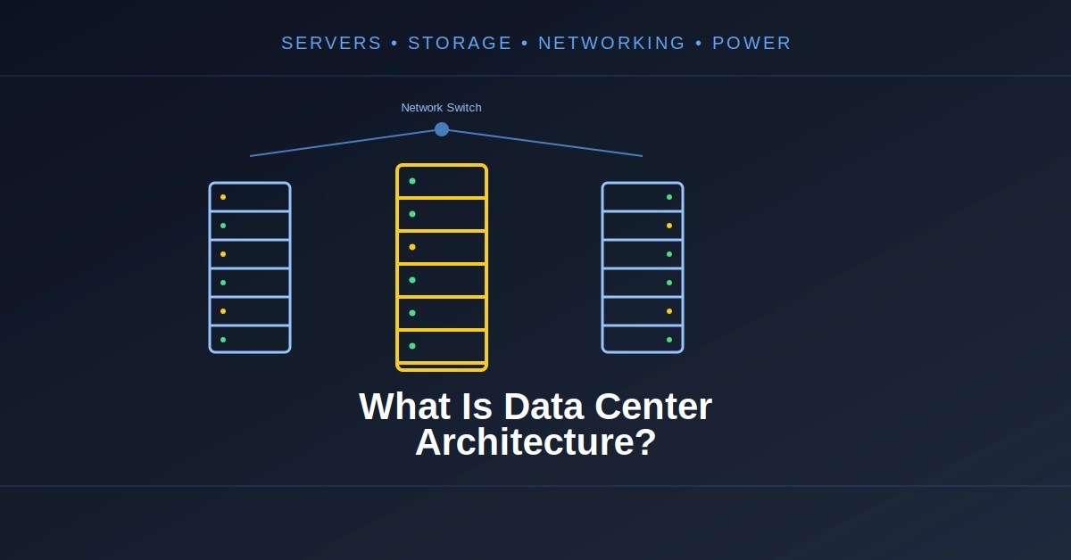
Data center architecture is the overall design of the physical and logical infrastructure used to provide computing services.
At the physical level, this includes:
- Servers
- Storage systems
- Network switches
- Routers
- Racks
- Power distribution
- UPS systems
- Generators
- Cooling equipment
- Cabling
- Physical security
At the logical level, it includes:
- Virtual machines
- Containers
- Networks
- Storage volumes
- Load balancing
- Software-defined infrastructure
- Monitoring
- Automation
- Resource scheduling
Cloud providers add another layer of abstraction on top of the physical infrastructure.
Google Cloud, for example, describes cloud architecture as a combination of hardware, virtualization, applications and services, with servers, storage and networking forming the underlying infrastructure. Google Cloud’s cloud architecture overview
A simplified architecture looks like this:
Users / Applications
        |
        v
   Network Layer
        |
        v
+-----------------------+
|    Compute Layer      |
|  Servers / CPUs / GPU |
+-----------------------+
        |
   +----+----+
   |         |
   v         v
Storage   Network
   |
   v
Data

Power + Cooling support every layer
The exact architecture changes depending on whether the facility is an enterprise data center, colocation facility, cloud region, hyperscale data center, or AI-focused facility.
The Four Core Components
A useful way to understand data center architecture is to divide the computing infrastructure into four major components:
1. Compute
The machines that execute workloads.
2. Network
The infrastructure that connects users, servers, storage and external systems.
3. Storage
The systems that hold operating systems, databases, files, applications and datasets.
4. Power
The electrical infrastructure that supplies and protects every component.
Cooling, security and facility management sit around these four pillars.
                Compute
                   |
                   |
Storage ------ Network ------ Users
                   |
                   |
                 Power
                   |
              Facility
The network is particularly important because it connects the other components.
Compute Architecture
Compute is the processing layer of a data center.
The most common compute resources are servers containing CPUs, memory, storage and network interfaces.
Depending on the workload, servers may also contain accelerators such as GPUs.
A simplified server looks like:
+--------------------------------+
|            Server              |
|                                |
|  CPU  CPU  CPU  CPU            |
|                                |
|  RAM RAM RAM RAM               |
|                                |
|  NVMe / SSD Storage            |
|                                |
|  Network Interface             |
|                                |
|  GPU GPU GPU   (optional)      |
+--------------------------------+
The CPU executes general-purpose instructions while memory provides working space for applications.
GPUs or other accelerators can handle specialized workloads such as AI, scientific computing, graphics or high-performance analytics.
Servers Are Usually Organized Into Racks
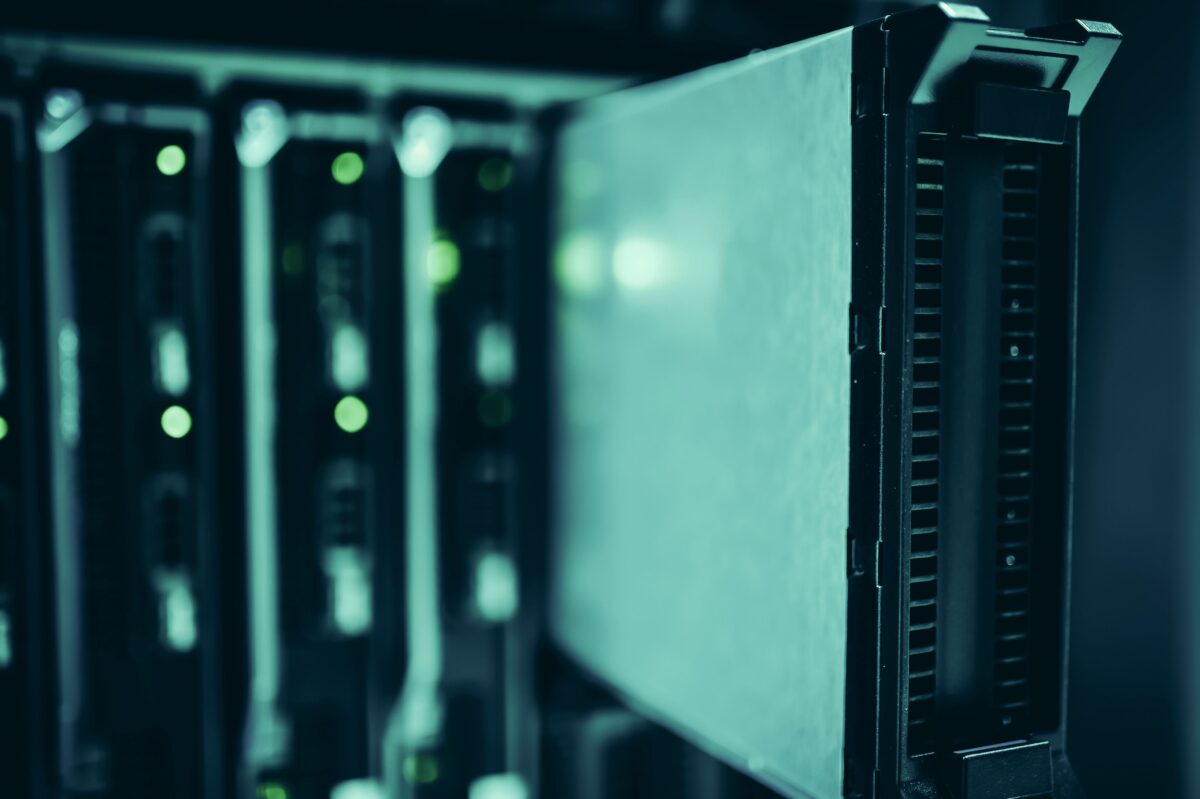
A data center does not normally place servers randomly around a building.
Servers are installed into standardized racks.
+----------------------+
| Server               |
+----------------------+
| Server               |
+----------------------+
| Server               |
+----------------------+
| Network Switch       |
+----------------------+
| Server               |
+----------------------+
| Server               |
+----------------------+
| Power Distribution   |
+----------------------+
A rack provides a standardized physical structure for mounting equipment and managing power, networking and airflow.
The rack also becomes an important unit of planning.
Operators need to know:
- How much power the rack consumes
- How much heat it generates
- How much network bandwidth it requires
- How much physical space it occupies
- How it connects to other racks
This becomes particularly important in GPU and AI data centers, where rack power density can be much higher than in traditional enterprise environments.
Compute Architecture Is About More Than CPUs
Modern data centers increasingly use heterogeneous computing.
A single facility may contain:
CPU Servers
GPU Servers
Storage Servers
Network Appliances
Specialized Accelerators
Each type of machine can be optimized for a different workload.
For example:
Web Application
      ↓
CPU Servers

AI Training
      ↓
GPU Cluster

Database
      ↓
High-Memory Servers

Object Storage
      ↓
Storage Nodes
This allows infrastructure operators to match hardware to workload requirements instead of using one server configuration for everything.
Virtualization Changes the Compute Layer
Physical servers can be divided into virtual machines using virtualization software.
For example:
Physical Server
       |
       v
Hypervisor
 ┌─────┼─────┐
 ↓     ↓     ↓
VM 1  VM 2  VM 3
Each virtual machine can run its own operating system and applications.
This creates an abstraction between physical hardware and software.
A cloud provider can therefore take a large pool of physical servers and present customers with virtual CPUs, memory, storage and networking.
Virtualization is one reason cloud infrastructure can provide resources on demand without requiring customers to manage physical servers themselves.
Network Architecture
The network is the communication layer of a data center.
It connects:
- Servers
- Storage systems
- Network devices
- Internet gateways
- Load balancers
- Security appliances
- Management systems
A simplified path might look like:
Internet
   |
Router
   |
Firewall
   |
Load Balancer
   |
Network Switch
   |
Server
But inside a large data center, networking becomes much more complicated.
Thousands of servers may need to communicate with each other simultaneously.
North-South and East-West Traffic
Data center traffic is commonly described using two directions.
North-South Traffic
Traffic moving between the data center and external users or networks.
User
  ↓
Internet
  ↓
Data Center
  ↓
Server
East-West Traffic
Traffic moving between systems inside the data center.
Server A ↔ Server B
     ↕          ↕
Server C ↔ Server D
East-west traffic is especially important in distributed applications, databases and AI workloads.
Modern hyperscale data centers can have enormous amounts of internal traffic. Google’s Jupiter network, for example, was designed to connect very large numbers of servers and storage systems with high aggregate bandwidth. Google’s explanation of Jupiter data-center networking
This is why data center networking cannot be treated simply as an enlarged office network.
How Data Center Switches Work Together
A large data center typically uses multiple layers of switching.
A simplified architecture might look like:
                Core / Spine
              /      |      \
             /       |       \
         Leaf       Leaf      Leaf
        / | \      / | \     / | \
      Server       Server    Server
This is often described using leaf-spine architecture.
The idea is to provide predictable paths between servers without forcing traffic through a long chain of network devices.
Large-scale operators can use variations of Clos-based architectures to scale network capacity.
Google has described its Jupiter network as using a Clos topology, software-defined networking and a large distributed switching fabric to connect compute and storage infrastructure at data-center scale. Google’s Jupiter network architecture
The exact topology varies by provider and workload.
Why Network Bandwidth Matters
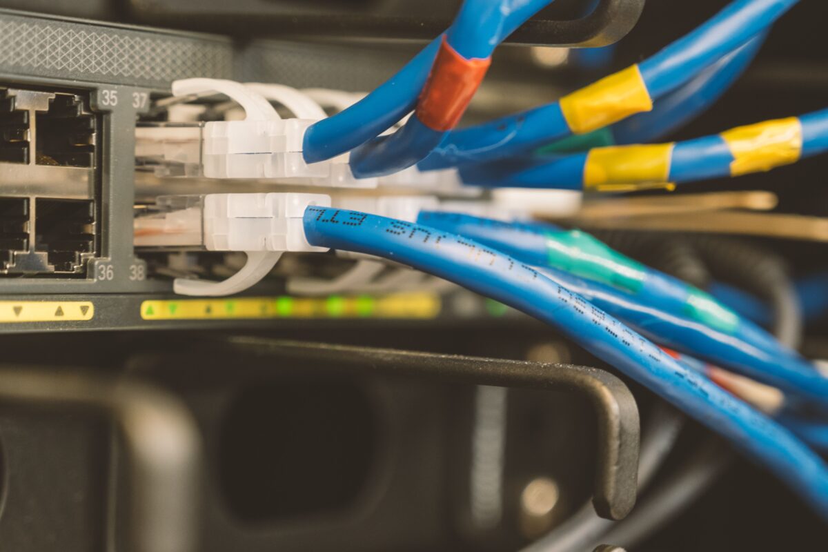
Imagine a server that can process data at 100 units per second but its network connection can deliver only 20 units per second.
The network becomes the bottleneck.
Compute Capacity
      100
       |
       X
       |
Network Capacity
       20
This problem becomes even more important for AI and high-performance computing.
A distributed AI workload may require many accelerators to exchange data repeatedly.
Google’s 2026 AI networking architecture separates scale-up accelerator communication, east-west scale-out traffic and north-south compute/storage access because modern AI workloads create very different networking requirements.
So modern network architecture is increasingly designed around the workload rather than just the number of servers.
Storage Architecture
Compute processes data.
Storage keeps it.
A data center may use several different types of storage depending on the workload.
Common technologies include:
- HDD
- SSD
- NVMe
- Distributed file systems
- Block storage
- Object storage
- Backup storage
A simple storage hierarchy looks like:
Application
    |
    v
Block / File / Object Storage
    |
    v
Storage Controllers
    |
    v
SSD / NVMe / HDD
Different storage types offer different combinations of:
- Capacity
- Latency
- Throughput
- Cost
- Reliability
Block Storage
Block storage presents storage as blocks that can be used by operating systems and applications.
It is commonly used for:
- Databases
- Virtual machines
- Enterprise applications
- Operating-system disks
A simplified structure is:
Application
     ↓
File System
     ↓
Block Device
     ↓
Storage System
File Storage
File storage organizes data into files and directories.
It is useful when multiple systems need access to shared files.
Examples include:
- Shared application data
- Engineering files
- Media
- Research datasets
Object Storage
Object storage uses objects rather than traditional hierarchical file structures.
It is particularly useful for very large quantities of unstructured data.
Examples include:
- Images
- Videos
- Backups
- Logs
- Data lakes
- Machine-learning datasets
Cloud providers commonly use object storage as a foundational storage service.
Why Storage and Network Architecture Are Connected
Storage is not isolated from networking.
In many modern systems, storage traffic travels across the same broader data-center network infrastructure that connects compute systems.
For example:
             Network
            /       \
           /         \
      Compute       Storage
This means storage performance can depend partly on network bandwidth and latency.
Google’s data-center networking architecture has historically been designed to support both distributed computing and storage systems, reflecting how closely these infrastructure layers are connected. Google’s overview of data-center networks
Modern infrastructure can also use dedicated or optimized paths for storage traffic when workloads require them.
Power Architecture
None of the computing infrastructure matters without electricity.
Power architecture is therefore one of the most critical parts of a data center.
A simplified power path looks like:
Utility Grid
     |
     v
Substation
     |
     v
Switchgear
     |
     v
UPS
     |
     v
Power Distribution
     |
     v
Rack PDU
     |
     v
Server
Each layer has a specific role.
Utility Power
The utility grid provides the primary electrical supply.
Large data centers can require substantial electrical capacity, so site selection often considers:
- Grid capacity
- Availability
- Expansion potential
- Transmission infrastructure
- Energy cost
- Renewable-energy availability
Power availability has become even more important as AI infrastructure increases compute density.
Google has noted that AI compute growth can exceed the space and power capacity of individual facilities, leading to architectures that distribute workloads across multiple connected sites.
UPS Systems
A UPS, or uninterruptible power supply, protects IT equipment from short interruptions and power-quality problems.
The basic idea is:
Normal Power
     ↓
    UPS
     ↓
 Servers
If utility power suddenly disappears, the UPS can provide temporary power while backup systems respond.
The UPS is not necessarily designed to run the entire facility indefinitely.
Its job is to bridge the transition between normal utility power and longer-duration backup generation.
Backup Generators
Data centers often use generators for longer-duration outages.
A simplified failure scenario looks like:
Utility Power
     X
     |
     v
   UPS
     |
     v
Generator Starts
     |
     v
Generator Power
     |
     v
Data Center
This creates multiple layers of protection.
The exact architecture varies depending on the facility’s reliability requirements.
Power Distribution Inside the Data Center
After power enters the facility, it has to be distributed to racks.
Power distribution equipment can include:
- Switchgear
- Transformers
- UPS systems
- Busways
- Power distribution units
- Rack PDUs
A rack may have multiple power feeds.
Power Feed A ───┐
                ├── Server
Power Feed B ───┘
This can allow equipment with redundant power supplies to continue operating if one power path fails.
Redundancy Is a Core Architectural Principle
Data centers are designed with the expectation that components can fail.
A server can fail.
A network switch can fail.
A power supply can fail.
A cooling unit can fail.
The architecture therefore tries to prevent a single failure from taking down the entire service.
This is known as redundancy.
A simple example is:
          Service
             |
       ┌─────┴─────┐
       ↓           ↓
   System A     System B
       |           |
       └─────┬─────┘
             ↓
          Storage
If System A fails, System B can potentially continue serving the workload.
Redundancy can exist at many levels:
Server redundancy
Network redundancy
Power redundancy
Cooling redundancy
Storage redundancy
Facility redundancy
The objective is not necessarily to duplicate everything.
The architecture is usually designed around the failure scenarios that the operator wants to tolerate.
What Does N+1 Mean?
One common redundancy model is N+1.
If a facility needs N units to operate normally, it has one additional unit available.
For example:
Required cooling units = 4

Installed:
Unit 1
Unit 2
Unit 3
Unit 4
Unit 5  ← extra capacity
If one unit fails, the remaining four can still provide the required capacity.
Other architectures may use N+2, 2N or different redundancy arrangements.
The correct design depends on cost, availability requirements and the consequences of failure.
Cooling Is Part of the Architecture
Power and compute cannot be separated from cooling.
Almost all electrical energy consumed by IT equipment eventually becomes heat.
That heat has to be removed.
A simplified thermal architecture is:
Electricity
    ↓
IT Equipment
    ↓
Heat
    ↓
Cooling System
    ↓
Heat Rejection
Traditional facilities often rely heavily on air cooling.
Modern high-density GPU infrastructure increasingly uses liquid cooling because accelerator power densities can be much higher.
Google has described data-center design as a system involving power delivery, cooling, server halls, compute, storage and networking rather than independent infrastructure components. Google’s data-center architecture discussion
Physical Layout of a Data Center
The building itself is normally divided into different areas.
A simplified facility might contain:
+---------------------------------------+
|              Data Center              |
|                                       |
|  +---------------------------------+  |
|  |          Server Hall            |  |
|  |                                 |  |
|  | Racks  Racks  Racks  Racks      |  |
|  |                                 |  |
|  +---------------------------------+  |
|                                       |
|  Power Infrastructure                 |
|  Cooling Infrastructure               |
|  Network Rooms                        |
|  Storage / Support Areas              |
|  Security / Operations                |
+---------------------------------------+
The exact layout varies considerably.
High-density AI facilities may require different mechanical and electrical arrangements from traditional enterprise facilities.
How the Components Work Together
The easiest way to understand data center architecture is to follow a request.
Suppose a user opens a cloud application.
User
 ↓
Internet
 ↓
Data Center Network
 ↓
Load Balancer
 ↓
Application Server
 ↓
Database / Storage
 ↓
Response
 ↓
User
But behind that simple request, several infrastructure systems are operating simultaneously.
Step 1: Network Receives the Request
The network infrastructure routes the user’s traffic toward the appropriate service.
Step 2: Compute Processes the Request
A server executes application code.
Step 3: Storage Provides Data
The application may need information from a database or storage system.
Step 4: Network Moves the Data
The requested information travels between systems.
Step 5: Power Supports Everything
Servers, switches and storage devices receive electrical power continuously.
Step 6: Cooling Removes Heat
The facility removes the heat generated by the IT equipment.
So the complete system is:
              User
                |
                v
             Network
                |
        +-------+-------+
        |               |
        v               v
     Compute         Storage
        |               |
        +-------+-------+
                |
              Power
                |
             Cooling
The application only sees a service.
Underneath that service is an entire physical infrastructure.
Data Center Architecture for Cloud Computing
Cloud providers add another important concept: resource pooling.
Instead of assigning one physical server permanently to one customer, cloud platforms can create pools of compute, storage and networking resources.
Physical Infrastructure
          |
    Resource Pool
          |
   +------+------+------+
   ↓      ↓      ↓      ↓
  VM     VM     VM     VM
Virtualization and software-defined infrastructure allow cloud providers to allocate resources dynamically.
A customer’s virtual machine may run on one physical server today and another later, depending on the provider’s architecture and workload management.
This abstraction is one of the foundations of cloud computing.
Data Center Architecture for AI
AI workloads are changing some parts of traditional architecture.
A conventional application might be relatively compute-heavy but have modest communication requirements between individual servers.
Large AI training jobs can be different.
GPU ↔ GPU ↔ GPU ↔ GPU
 ↕     ↕     ↕     ↕
GPU ↔ GPU ↔ GPU ↔ GPU
The GPUs may continuously exchange data.
That increases the importance of:
- Network bandwidth
- Network latency
- GPU interconnects
- Storage throughput
- Power density
- Cooling capacity
Google’s 2026 AI networking architecture describes separate scale-up and scale-out network domains specifically for tightly coupled accelerator workloads.
This is one reason an AI data center cannot always be designed simply by taking a traditional data-center architecture and adding more GPUs.
Data Center Architecture Is Becoming More Modular
Modern data centers increasingly need to accommodate hardware generations that change quickly.
A facility built today may need to support different CPUs, GPUs, networking equipment and storage systems several years later.
This encourages modular designs.
For example:
Power Module
     +
Cooling Module
     +
Compute Module
     +
Network Module
     +
Storage Module
Each component can potentially be upgraded without rebuilding the entire facility.
Google has described modularity, interoperability and the ability to reuse infrastructure across hardware generations as important principles for modern data-center design.
This becomes particularly important for AI infrastructure because accelerator generations can change rapidly.
Failure Domains
Another important architectural concept is the failure domain.
A failure domain is a group of infrastructure components that could be affected by the same failure.
For example:
Zone A
 ├── Servers
 ├── Network
 └── Power

Zone B
 ├── Servers
 ├── Network
 └── Power
If both zones are sufficiently independent, a failure affecting Zone A does not necessarily affect Zone B.
Cloud providers commonly use regions and zones to create separate failure domains. Google’s cloud networking documentation, for example, describes zones as deployment areas designed with independent failure domains. Google Cloud networking architecture
At larger scales, redundancy can extend beyond a single room or building.
Data Center Architecture Is a Trade-Off
There is no single perfect data-center architecture.
Every design involves trade-offs between:
- Cost
- Performance
- Availability
- Energy efficiency
- Scalability
- Complexity
- Physical space
- Maintainability
For example, doubling a component may increase resilience but also increase cost.
A high-bandwidth network may improve application performance but require more expensive switching equipment and power.
Liquid cooling can enable higher compute density but introduces additional mechanical infrastructure.
The architecture therefore has to match the workload and business requirements.
Traditional vs AI-Oriented Architecture
The differences can be summarized like this:
| Component | Traditional Data Center | AI-Oriented Data Center |
|---|---|---|
| Compute | CPU-focused | GPU/accelerator-heavy |
| Network | General-purpose | High-bandwidth, low-latency |
| Internal traffic | Moderate to high | Potentially extremely high |
| Storage | General-purpose | High-throughput data pipelines |
| Rack density | Usually moderate | Can be very high |
| Cooling | Often air-based | Air and increasingly liquid |
| Power | Conventional distribution | Higher-density power delivery |
| Optimization | Server/service level | Rack, cluster and facility level |
| Communication | Often application-dependent | Critical to distributed training |
| Architecture | General-purpose | Workload-specific |
Not every AI facility uses every technology listed in the AI column.
The architecture depends on the workload, accelerator platform and scale.
The Data Center as One Computer
At hyperscale, it becomes difficult to think of the data center as a collection of independent servers.
The architecture starts looking more like a distributed computer.
                 DATA CENTER
                     |
       +-------------+-------------+
       |             |             |
    Compute       Network       Storage
       |             |             |
       +-------------+-------------+
                     |
                   Power
                     |
                  Cooling
The network connects the computing resources.
Storage provides the data.
Power supplies the hardware.
Cooling keeps the hardware operating.
Software coordinates the entire system.
This is the fundamental idea behind modern warehouse-scale and hyperscale computing.
Google’s evolution of the Jupiter network is a good example: the network was designed as a large-scale fabric supporting distributed computing and storage rather than simply connecting a small collection of independent servers.
Final Takeaway
Data center architecture is the design of the systems that allow computing infrastructure to operate as one reliable, scalable platform.
The four core pillars are:
              DATA CENTER
                   |
     ┌─────────────┼─────────────┐
     ↓             ↓             ↓
  Compute       Network       Storage
     |             |             |
     └─────────────┼─────────────┘
                   ↓
                 Power
                   +
              Cooling
Compute performs the work.
Network moves information between users, servers and storage.
Storage holds the data applications need.
Power provides the energy required by every component.
Cooling removes the resulting heat.
Redundancy, security, monitoring and automation then make the whole system reliable and manageable.
As AI and other high-performance workloads continue to grow, these architectural layers are becoming increasingly interconnected. Data centers are no longer simply buildings full of servers. They are large-scale computing systems in which hardware, networking, storage, power and cooling have to be engineered together.
That systems-level architecture is what allows a modern data center to scale from a handful of servers to infrastructure supporting thousands of machines and increasingly, large distributed AI clusters.
SiliconeUpdate.com is a technology news platform that publishes updates and informational content related to silicon technology, software, artificial intelligence, and emerging technologies.
All articles published on this platform are attributed to SiliconeUpdate.com instead of individual authors. Content is presented in a neutral, informational format without personal opinions.
—
Content Publishing
SiliconeUpdate.com publishes news and updates based on publicly available information, official announcements, and industry developments. The focus is on clarity, relevance, and timely reporting.
—
Editorial Control
All editorial decisions, updates, and content management are handled at the platform level. No individual human or AI identity is presented as the author of articles.
—
Contact
For editorial communication or general queries, contact:
Email: neemasharma@gmail.com